The Field page allows you to specify how tables are grouped within the DC Field, using the module, string, and rack configurations defined on the Table page. An automated visual representation of the DC Field layout is displayed on the right side, showing the arrangement of rows and tables with calculated dimensions.Documentation Index
Fetch the complete documentation index at: https://docs.plantpredict.com/llms.txt
Use this file to discover all available pages before exploring further.
Overview
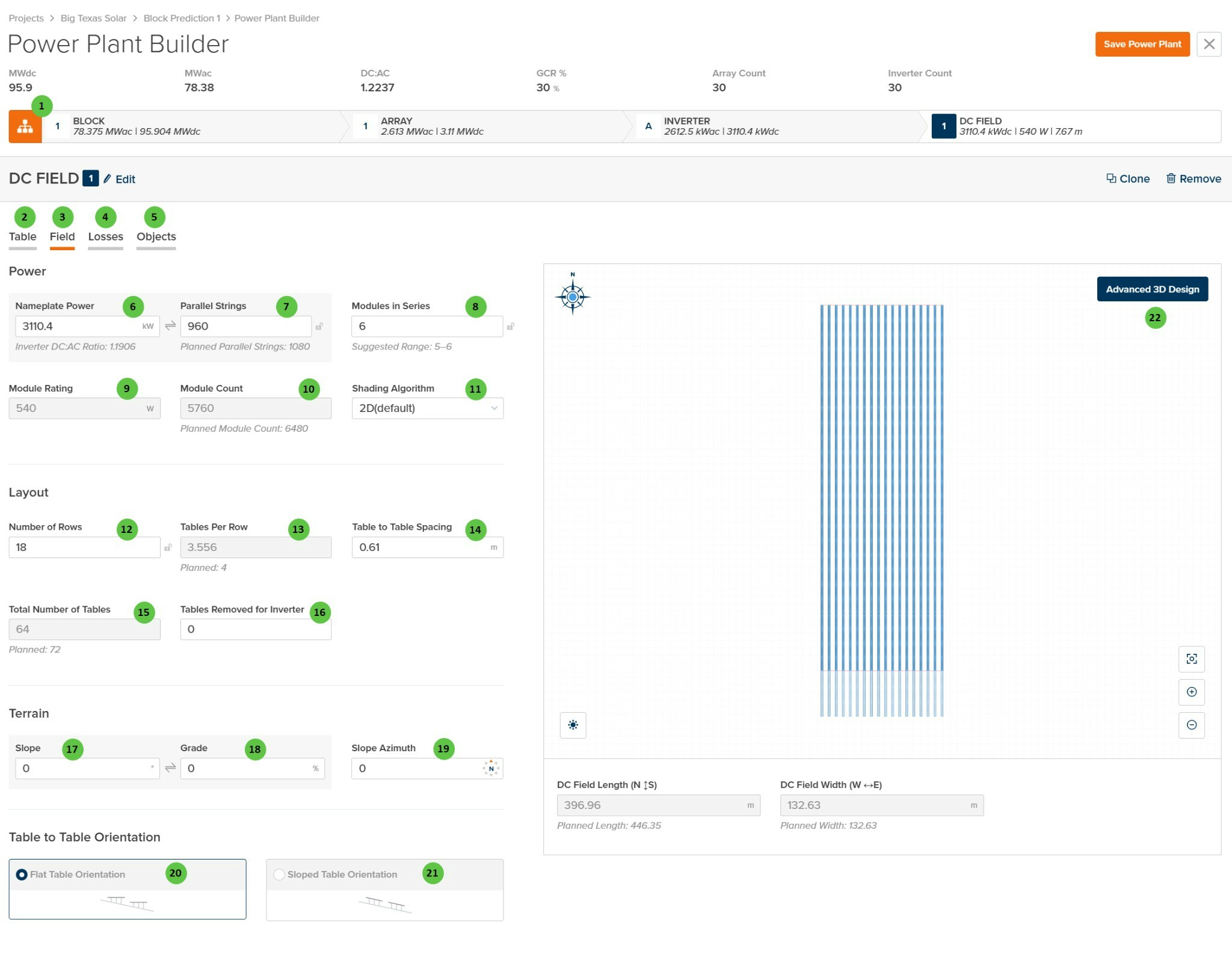
The DC Field - Field page is organized into the following sections:- DC Field Header — Shows the DC Field identifier with Edit, Clone, and Remove buttons.
- Tab Navigation — Access different aspects of DC Field configuration: Table, Field, Losses, and Objects.
- Power — Configure the electrical capacity including nameplate power, parallel strings, modules in series, and shading algorithm selection.
- Layout — Define the physical arrangement of tables including number of rows, tables per row, spacing, and total table count.
- Terrain — Specify ground slope parameters for the DC Field location.
- Table to Table Orientation — Select whether tables follow flat or sloped terrain orientation.
- DC Field Visualization — Interactive preview showing the field layout with calculated dimensions (N-S length and E-W width).
User Inputs
| # | Input | Type | Units | Description | Related Documentation |
|---|---|---|---|---|---|
| 1 | Edit (DC Field) | Button | — | Opens a dialog to edit the DC Field name and repeater count. | — |
| 2 | Table (Tab) | Tab | — | Navigate to the Table tab to configure module selection, mounting type, and table geometry. | Table |
| 3 | Field (Tab) | Tab | — | Currently selected tab. Contains DC Field layout, power configuration, and terrain settings. | — |
| 4 | Losses (Tab) | Tab | — | Navigate to the Losses tab to configure DC field losses including mismatch, wiring losses, and thermal model parameters. | Losses |
| 5 | Objects (Tab) | Tab | — | Navigate to the Objects tab to configure near-field shading objects specific to this DC Field (legacy workflow). | Objects |
| 6 | Nameplate Power | Text Field | kW | The total DC nameplate power of the DC Field. Calculated from Module Rating × Module Count. Displays the Inverter DC:AC Ratio below for reference. | — |
| 7 | Parallel Strings | Text Field | — | Number of strings connected in parallel to the inverter from this DC Field. “Planned Parallel Strings” shown below indicates the target value based on inverter sizing. | — |
| 8 | Modules in Series | Text Field | — | Number of modules connected in series per string. The “Suggested Range” indicates valid values based on inverter voltage limits and module Voc/Vmp characteristics. | — |
| 9 | Module Rating | Display | W | The rated power of the selected module. This value is read-only and is set on the Table tab via module selection. | — |
| 10 | Module Count | Text Field | — | Total number of modules in the DC Field. Calculated from Parallel Strings × Modules in Series. “Planned Module Count” indicates the target based on layout. | — |
| 11 | Shading Algorithm | Dropdown | — | Select the shading calculation method. Options: 2D (default), Infinite Length Rows, 3D (Legacy). | Row-to-Row Beam Shading |
| 12 | Number of Rows | Text Field | — | The number of tracker or fixed-tilt rows in the DC Field. Use the sync icon to toggle between linked and manual modes. | — |
| 13 | Tables Per Row | Text Field | — | Average number of tables per row. May be a decimal if rows have varying table counts. “Planned” value shown below indicates the target configuration. | — |
| 14 | Table to Table Spacing | Text Field | m / ft | Horizontal gap between adjacent tables along a row. Used for layout visualization and land area calculations. | — |
| 15 | Total Number of Tables | Text Field | — | Total count of tables in the DC Field. Calculated from Number of Rows × Tables Per Row, minus any removed tables. “Planned” value indicates target. | — |
| 16 | Tables Removed for Inverter | Text Field | — | Number of tables removed from the layout to accommodate inverter pad placement or other obstructions. | — |
| 17 | Slope | Text Field | degrees | Ground slope angle of the DC Field terrain. Affects bifacial calculations and terrain-aware backtracking if enabled. | Terrain-Aware Backtracking |
| 18 | Grade | Text Field | % | Ground slope expressed as a percentage (rise/run × 100). Linked to Slope field — editing one updates the other. | — |
| 19 | Slope Azimuth | Text Field | degrees | Compass direction of the downhill slope (0° = North, 90° = East, 180° = South, 270° = West). | — |
| 20 | Flat Table Orientation | Radio Button | — | Tables are oriented horizontally regardless of terrain slope. Standard configuration for level or gently sloped sites. | — |
| 21 | Sloped Table Orientation | Radio Button | — | Tables follow the terrain slope, maintaining consistent height above ground across sloped terrain. | — |
| 22 | Advanced 3D Design | Button | — | Opens the advanced 3D design interface for detailed field layout customization, including individual row placement and terrain modeling. | 3D Shading |