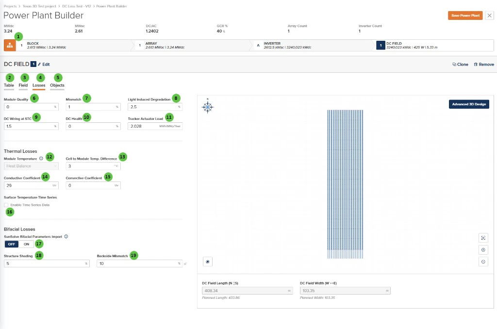
The Losses page allows you to specify DC-side losses for the DC Field, including module quality factors, mismatch losses, wiring losses, and thermal model parameters. These inputs directly affect energy yield calculations by accounting for real-world inefficiencies in the DC system.Documentation Index
Fetch the complete documentation index at: https://docs.plantpredict.com/llms.txt
Use this file to discover all available pages before exploring further.
Overview
The DC Field - Losses page is organized into the following sections:- DC Field Header — Shows the DC Field identifier with Edit, Clone, and Remove buttons.
- Tab Navigation — Access different aspects of DC Field configuration: Table, Field, Losses, and Objects.
- DC Losses — Configure percentage-based losses for module quality, mismatch, degradation, wiring, and health factors, plus tracker power consumption.
- Thermal Losses — Configure the module temperature model including heat balance parameters and temperature coefficients.
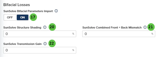
- Bifacial Losses — Standard structure shading and backside mismatch inputs, or optional SunSolve-style parameters when SunSolve Bifacial Parameters Import is enabled (see rear irradiance).
- Surface Temperature Time Series — Enable custom time series data for module surface temperature.
- DC Field Visualization — Preview of the field layout for reference.
User Inputs
| # | Input | Type | Units | Description | Related Documentation |
|---|---|---|---|---|---|
| 1 | Block (Hierarchy) | Button | — | Toggle view to show the Block-level hierarchy bar displaying system summary: MWdc, MWac, DC:AC ratio, GCR, Array Count, and Inverter Count. | Block Overview |
| 2 | Table (Tab) | Tab | — | Navigate to the Table tab to configure module selection, mounting type, and table geometry. | Table |
| 3 | Field (Tab) | Tab | — | Navigate to the Field tab to configure string count, layout arrangement, terrain, and field-level settings. | Field |
| 4 | Losses (Tab) | Tab | — | Currently selected tab. Contains DC loss factors and thermal model configuration. | — |
| 5 | Objects (Tab) | Tab | — | Navigate to the Objects tab to configure near-field shading objects specific to this DC Field (legacy workflow). | Objects |
| 6 | Module Quality | Text Field | % | Percentage loss due to module manufacturing quality variation from nameplate rating. Positive values indicate underperformance relative to rated power. | DC Losses |
| 7 | Mismatch | Text Field | % | Percentage loss due to electrical mismatch between modules in a string or array. Accounts for variations in module I-V characteristics. | DC Losses |
| 8 | Light Induced Degradation | Text Field | % | Percentage loss from initial light-induced degradation (LID) that occurs in the first hours of module operation. Applies primarily to crystalline silicon modules. | DC Losses |
| 9 | DC Wiring at STC | Text Field | % | Percentage loss in DC wiring and connections at Standard Test Conditions (STC). Includes string wiring, combiner boxes, and DC home runs. | DC Losses |
| 10 | DC Health | Text Field | % | Percentage loss representing ongoing DC system degradation and health issues not captured by other loss categories. Can be used for aging adjustments. | DC Losses |
| 11 | Tracker Actuator Load | Text Field | MWh/MWp/Year | Annual energy consumption of tracker motors and actuators, expressed per MWp of DC capacity. Only applicable to tracker-mounted systems. | — |
| 12 | Module Temperature | Dropdown | — | Select the module temperature calculation method. Options: Heat Balance, Sandia, NOCT. | Module Temperature |
| 13 | Cell to Module Temp. Difference | Text Field | °C / °F | Temperature offset between the module backsheet (measured) and cell junction temperature. Accounts for thermal resistance within the module. | Module Temperature |
| 14 | Conductive Coefficient | Text Field | Uc | Conductive heat transfer coefficient (Uc) for the heat balance model. Represents constant heat loss independent of wind speed. | Module Temperature |
| 15 | Convective Coefficient | Text Field | Uv | Convective heat transfer coefficient (Uv) for the heat balance model. Represents wind-dependent heat loss; multiplied by wind speed in the thermal calculation. | Module Temperature |
| 16 | Enable Time Series Data | Checkbox | — | When enabled, allows import of custom module surface temperature time series data instead of using the calculated thermal model. | — |
| 17 | SunSolve Bifacial Parameters Import | Toggle | — | When ON, PlantPredict uses the SunSolve-style inputs below and applies the rear-irradiance adjustment documented for SunSolve import on Rear (bifacial) plane-of-array irradiance (for example, combined front + back mismatch overrides the Mismatch value in General DC Losses, and transmission-related handling follows the in-app tooltips). When OFF, use Structure Shading and Backside Mismatch in this section. | Rear (bifacial) plane-of-array irradiance |
| 18 | Structure Shading | Text Field | % | Rear-side loss from structure shading. Shown when SunSolve Bifacial Parameters Import is OFF. | Rear (bifacial) plane-of-array irradiance |
| 19 | Backside Mismatch | Text Field | % | Mismatch on the back side. Shown when SunSolve Bifacial Parameters Import is OFF. | Rear (bifacial) plane-of-array irradiance |
| 20 | SunSolve Structure Shading | Text Field | % | Shown when SunSolve Bifacial Parameters Import is ON (0–100%). | Rear (bifacial) plane-of-array irradiance |
| 21 | SunSolve Combined Front + Back Mismatch | Text Field | % | Shown when SunSolve Bifacial Parameters Import is ON (0–100%). Overrides the Mismatch value under General DC Losses while import is on. | Rear (bifacial) plane-of-array irradiance |
| 22 | SunSolve Transmission Gain | Text Field | % | Shown when SunSolve Bifacial Parameters Import is ON (0–100%). System-level gain applied in the rear-irradiance model; use the in-app info tooltip to avoid double-counting with module-level transmission settings. | Rear (bifacial) plane-of-array irradiance |
| 23 | Advanced 3D Design | Button | — | Opens the advanced 3D design interface for detailed field layout customization, including individual row placement and terrain modeling. | 3D Shading |